AstroDMx Capture – INDI Walk-through
1: Overview
This section is intended to take the user on a brief walk-through to demonstrate how to use the new functionality of AstroDMx Capture. It is not intended to be an in depth instruction manual, however, completing this walk-through should give you a solid grounding in how to use the new features of AstroDMx Capture on real Astronomical objects.
IMPORTANT: AstroDMx Capture automatically calculates the correct date and time values which includes the appropriate daylight saving offset. It is therefore important to make sure that the mount hand controller’s daylight saving setting is not switched on. If daylight saving is active on the mount’s hand controller, then objects could be missed by 15 degrees.
One great feature of INDI is the ability to use simulators. These simulators operate almost identically to using real INDI devices but have the advantage of being used regardless of the weather or time of day. If set up correctly, the simulated CCD device will show an accurate starfield based on supplied celestial coordinates from the simulated mount. The simulators are a great way to experiment with the new features of AstroDMx Capture without waiting for a clear night.
Let’s look at an example. If the simulated mount is sent to RA 13h 23m 54s and DEC 54° 55m 31s, which is the celestial coordinates for the star Mizar, then the simulated CCD will actually show the naked eye double, Mizar and Alcor on the preview screen of AstroDMx Capture.

The INDI simulators can be used in conjunction with planetarium software. The following screenshot shows Stellarium being used to verify that the simulated mount is indeed centred on Mizar.

As far as AstroDMx Capture is concerned, there is absolutely no difference between using the simulators or a real world INDI device. The benefits of learning to use AstroDMx’s advanced features in this manner are clear. One can become proficient in the use of the software without having to wait for a clear night or potentially waste a rare opportunity to image because one does not understand how to use AstroDMx Capture.
For the purposes of this walk-through, the star, Mizar, will be used. The reason is that, as it is a double star, it is very easy to recognise on the preview screen. Both Mizar and Alcor can be clearly seen.
2: What is INDI?
INDI is an acronym of Instrument Neutral Distributed Interface. It is a distributed control system protocol to enable control, data acquisition and exchange of data between a centralised server, astronomical devices and client software.
In short, INDI allows the astronomer to control their telescopes, cameras, filter wheel and focusers from a remote location over an existing wired or wireless TCP/IP network. This removes the need for the user to be situated at the telescope during an imaging session.
Server Software
The INDI server must be run on a POSIX compliant system. Generally speaking, the INDI server is run on a Linux or a macOS system but it should be possible to run it on other POSIX systems such as FreeBSD but with limited driver support. In this article, we will discuss installing the INDI server on a Debian based Linux distribution. Other operating systems will most likely have to be built from source and so are outside the scope of this documentation.
It has been shown that the INDI server can be run on Windows via a Linux virtual machine. For more information see this blog post.
Driver Software
The driver software sits between the server and hardware. The driver has to be selected to match the hardware which is intended to be used. In this article, we will be using the INDI simulators to learn how to use AstroDMx. In this context, the simulators are the INDI drivers.
Client Software
The client software connects to an INDI server and is able to see and communicate with the drivers that have been configured on that specific INDI server. These drivers, for example, could be mounts, cameras, filter wheels or focusers. In the context of this article, AstroDMx Capture is an INDI client.
3: Installing an INDI server
As mentioned above, the INDI server can run on any POSIX compliant operating system, however, this article will only discuss installing on a Debian Linux distribution.
This stage should be completed on the computer that you wish to use as the INDI server. This could be the same computer where AstroDMx Capture is run or a separate computer, such as a Raspberry Pi. If running on a separate Linux computer, then SSH will need to be enabled. SSH is a method of securely accessing a remote computer.
Installing INDI
The installation procedure is as follows. Simply copy and paste the following commands into a terminal window.
- sudo apt-add-repository ppa:mutlaqja/ppa
- sudo apt-get update
- sudo apt-get install indi-full gsc
If installing the INDI server on a remote machine, then complete the following to install SSH. If the server is being installed on the same machine that runs AstroDMx Capture then this stage is not required and so can be safely missed.
Installing SSH
- sudo apt-get install openssh-server
- sudo systemctl enable ssh
- sudo systemctl start ssh
Once SSH is installed, it is necessary to find out the IP address of the remote computer as this will be needed when setting up AstroDMx Capture. To obtain the IP address, simply type the following and note the IP address.
- hostname -I
This concludes the section on installing an INDI server.
4: Configure an INDI server
This part of the walk-through will detail how to configure an INDI server using AstroDMx Capture. It will specifically detail how to install and activate the INDI simulator drivers but, as mentioned above, the fact that we are using simulators is irrelevant. The same procedure is used to connect to real devices. The only difference is that the actual hardware would have to be connected to the computer designated as the INDI server before the drivers are started.
Starting an INDI server
AstroDMx Capture has a simple graphical user interface to start, stop and configure INDI devices. Make sure the computer that is running the INDI server is powered up and then complete the following steps.
- Start AstroDMx Capture
On the left hand side of AstroDMx Capture’s UI are various controls specific to INDI devices. Under the “General” group you should see four buttons. These buttons are labelled, “Equipment”, “Site Location”, “INDI Control Panel” and “INDI Configurator”. The control that we are currently interested in is the button labelled, “INDI Configurator”. Press this button and you should see the following window.

This window holds all the functionality required to start, stop and configure an INDI server. This stage must be completed before any INDI functions can be used within AstroDMx Capture. Looking at the screenshot above, you should notice that areas have been highlighted in various colours. This colour coding scheme will be used below.
For the rest of this walk-through we will operate on the basis that the INDI server is installed on a separate machine. If your INDI server is installed locally then all you need to do is to set “Local Computer” at step 1 and miss out steps 2 and 3. The rest is identical.
The Procedure
- Click on the “Mode” drop-down menu and select “Remote Computer”.
- Click the “Server Login” button.
- Enter the IP address of the remote INDI server.
- Enter the username and password for that remote server.
- Click “Connect”.
- If successful, you should see a message that says “SSH: Connected”. When you see this message, click “OK” to return to the previous window.
- If you see an error message, then check that the remote computer is running and that you have specified the correct IP address, username and password. The error message should give you some insight into what has gone wrong.
- Once you return to the previous window, you should see a green light in the area highlighted in yellow (see screenshot above). This means that we have successfully connected to the computer where the INDI server is installed. We are now ready to start and configure the INDI server itself.
- AstroDMx will now look in the default path for an INDI server. If it is able to find an INDI server then the buttons highlighted in blue (above) will become available. If an INDI server was not found and you have an INDI server located in a non standard path, you should click the “Set Path” button to specify the non standard path to the INDI server.
- Click “Start Server” which is highlighted in blue above.
- Wait a few seconds for the INDI server to start. Once started, the “Add Driver” button (highlighted in green) should become available. If the server fails to start, then look at the log to see what might have gone wrong.
- Click the “Add Driver” button. This will bring up another window which shows all the available INDI drivers. As previously mentioned, we are using the simulators in this walk-through but if you were using a real device, then you would simply select that device instead of a simulated device. Once the “Add INDI Driver” window opens, follow this procedure.
- Navigate to “CCDs” and expand this group.
- Roll down until you find “Simulator” and expand this group.
- Double click on “CCD Simulator”. This will return you to the previous window.
- Click the “Add Driver” button again.
- Navigate to “Telescopes” and expand this group.
- Roll down until you find “Simulators” and expand this group.
- Double click on “Telescope Simulator”
- Steps 1 through to 7 should populate the UI with the simulator drivers. These drivers will be available in the “INDI Driver” drop-down menu (highlighted in red above).
- Use the drop-down menu (highlighted in red) and select “Telescope Simulator”.
- Click “Start Driver”. This should inject the simulator driver into the remote INDI server and start it. If all is successful, then “Start Driver” will change to “Stop Driver” and you should see a message in the server log area indicating that the driver has started and is ready to use.
- Use the drop-down menu (highlighted in red) and select “CCD Simulator” and repeat step 10.
If steps 1 to 11 have been successful, then all the lights should be green and look similar to the screenshot below. This indicates that your INDI server has been configured to use the simulator drivers and that they are ready to use within AstroDMx Capture.

This concludes the section on configuring an INDI server.
5: Configure the INDI Simulators
This section is only required to configure the INDI simulators. It would not be required for a normal imaging session. We will configure our simulated telescope with an aperture of 80mm and a focal length of 500mm.
The Procedure
- Under the “General” group, click “INDI Control Panel”.
- Enter the IP address of where your INDI server is located.
- Click “Login”.
- Click the “Telescope Simulator” tab.
- Click the “Options” tab.
- Roll down until you see “Scope Properties”
- Under “Scope Properties – Aperture”, enter 80
- Under “Scope Properties – Focal Length”, enter 500
- Under “Scope Properties – Guider Aperture”, enter 80
- Under “Scope Properties – Guider Focal Length”, enter 500
- Click the large “Set Button”.
- Close the “INDI Control Panel” window.
Initially, it may look odd to use imaging and guiding scopes of the same focal length, however, this has been done to simplify the simulation setup.
The window should now look like this.

6: Connecting to an INDI Mount
Once you have completed the previous steps, you are ready to connect to the mount and use all the features offered by that mount. The mount control functionality can be found under the heading “Controls: Mount”. The controls in this group area split into two discrete subgroups. The first subgroup is for the initial connection and the second is for controlling the mount.

To change between the connection and the mount controls, you use two buttons at the very top of the “Controls: Mount” group (see the screenshot above). The left hand button will expose the connection controls and the right will expose the mount controls. At this stage, the location of the INDI server is irrelevant as long as the correct IP address is entered.

The screenshot above shows the INDI connection controls.
The Procedure
- Enter your INDI server’s IP address under the “INDI Host” section. If the INDI server is running on the same machine as AstroDMx Capture, then you enter “localhost” otherwise enter the IP address of the machine where the INDI server is located. You almost certainly will never need to change the port parameter.
- Click “Connect INDI Server”. This will cause AstroDMx to attempt to connect to the actual INDI server. If successful, the label on the button will change to “Disconnect INDI Server”. If this stage fails, then check the log at the bottom of the AstroDMx main UI. This should give some insight as to what has gone wrong.
- Select “Telescope Simulator” under the “Mount” drop-down menu.
- Click “Connect”. If this is successful, then the button’s label will change to “Disconnect”. If this stage fails, then check the log at the bottom of the AstroDMx main UI.
- If this is your first time using AstroDMx, then you will see a message that informs you that your geographical location is not set. If your geographic location is already set then you will not see this message.
- You should now be connected to the simulated mount. If at step 5 you received a message about your geographic location, then continue otherwise miss the geographical location section below and start at “Set Date and Time”.
Geographic location
Clicking “Yes” on the message about your geographic location will present you with the following window. This window will allow you to enter your latitude, longitude and altitude information. Multiple locational information can be added based on specifying a profile name. This information can be populated from a connected mount or used to update a mount’s hand controller.
As we are using the simulators for the first time, there will be no location information available so this must be added now.
The Procedure
- Click “Add Profile”, specify a name and then click “Apply”.
- Enter your latitude, longitude and elevation.
- Click “Set Mount’s Location” to update the mount with this information.
- Click “Set Location” to use this as an active geographical location.
Once populated the UI should look like the screenshot below.

The geographical location window showing the coordinates of the Royal Observatory Greenwich. The Royal Observatory is situated only a few arcseconds from the prime meridian.
Location profiles can be added, renamed or deleted. If you wish to use a different location, simply select that location from the drop-down menu and then click “Set Mount’s Location” and then “Set Location”. This will update the mount hand controller to reflect the new location.
The latitude and longitude need to be entered in the sexigesimal format (Degrees, Minutes, Seconds).
Set Date and Time
Setting the mount’s date and time is easy with AstroDMx Capture. AstroDMx automatically takes the user’s local time and daylight saving into account and will send the accurate time to the mount.
It is vital that your computer’s clock is set accurately otherwise the incorrect time will be sent to the mount. If your computer’s clock is not accurate, then you can set the date and time manually by clicking on the “Set Manually” button.
The date and time settings can be found under the INDI telescope mount drop-down menu. Click the “Mount Date/Time” button and you should see the following window.

If you check the “Automatically Set Mount Time at Connect”, then every time AstroDMx connects to a mount, it will automatically update the mount’s date and time values. In order to set the date and time manually, simply click the “Set Mount Time” button.
Once complete, click “Close”.
This concludes the section on connecting to an INDI mount.
7: Connecting to an INDI Camera
The procedure for connecting an INDI camera is very similar to connecting to a mount device. The control group falls under the heading “Controls: Camera (INDI)” and looks like the following screenshot.

The Procedure
- Enter your INDI server’s IP address under the “INDI Host” section. If the INDI server is running on the same machine as AstroDMx Capture, then you enter “localhost” otherwise enter the IP address of the machine where the INDI server is located.
- Click “Connect INDI Server”. This will cause AstroDMx to attempt to connect to the INDI server. If successful, the label on the button will change to “Disconnect INDI Server”. If this stage fails, then check the log at the bottom of the AstroDMx main UI. This should give some insight as to what has gone wrong.
- Select “CCD Simulator” under the “Camera Select” drop-down menu.
- Click “Connect”. If this is successful, then the button’s label will change to “Disconnect” and the light will change to green. If this stage fails, then check the log at the bottom of the AstroDMx main UI.
- Select the pixel format that you wish to use. In the case of the “CCD Simulator”, we will select “Mono”.
- Select the correct mode, currently the only option implemented is “RAW / FITS”.
- Click the “Start Camera” button.
After clicking “Start Camera” you should see the preview screen come to life and it will be displaying a changing noise pattern. This means that the simulated CCD is streaming live data. We can now take a few minutes to optimise this live image stream in preparation for the next stage.
Optimising the CCD camera stream
On the right hand side of AstroDMx Capture are the usual controls that many users will be familiar with. These controls allow the user to change parameters such as exposure, gain, preview screen transforms and thermal controls etc. We will now use these controls to adjust the exposure of the CCD simulator and activate its cooler.
The Procedure
- On the right hand side of AstroDMx, under the group “Controls: Exposure”, set the gain to 100.
- Under the same group, set the exposure to 5 seconds by typing “5s” and pressing enter. This will cause AstroDMx to enter its long exposure mode and you will see the exposure progress bar start to countdown from 5 seconds and continuously repeat.
- In order to clearly see the simulated stars we need to adjust the preview transform. To do this, navigate to “Controls: Preview Controls” (on the right hand side) and under “Preview Transform” select “ArcSimH Stretch”. You may need to adjust the Stretch and black point parameters of this transform.
- Go to “Controls: Thermal” on the right hand side of AstroDMx and turn on the cooler and set a target temperature of -20 degrees.
Once you have done this, you should be able to see a simulated starfield. This is a realistic starfield which is based upon the current coordinates of the simulated mount. If you have followed this procedure accurately and the settings are default, this will be at RA 23h 59m 24s and DEC 89d 52m 15s (J2000 epoch). Basically, very near to the north celestial pole.
This concludes the section on connecting an INDI camera.
8: Controlling an INDI Mount
IMPORTANT: AstroDMx Capture automatically calculates the correct date and time values which includes the appropriate daylight saving offset. It is therefore important to make sure that the mount hand controller’s daylight saving setting is not switched on. If daylight saving is active on the mount’s hand controller, then objects could be missed by 15 degrees.
At this point we should have the INDI simulated mount and simulated CCD connected and you should be able to see a simulated starfield on the preview screen. In addition to this, the mount should be pointing at the north celestial pole.
We are now ready to start experimenting with mount operations. In order to do this, go back to “Controls: Mount” and click the right-hand button (at the very top) to change from connection mode to control mode (see the screenshot directly above).
This is the main UI to control INDI mounts. This includes pointing information, GOTO requests, nudging functions, tracking control, slew rate control and mount parking/unparking. GOTOs can be performed by manually entering celestial coordinates in the J2000 epoch, from the built-in object database or from astrometry. Astrometry will be detailed later in this walk-through.

Before we start experimenting with mount operations, we will take a break from the walk-through and have a closer look at the components of this particular UI. Starting from the top and working down, the components are as follows.
Celestial Coordinates: Right Ascension and Declination

The green area shows the coordinates where the mount is currently pointing. They are reported in the J2000 epoch and so may be different to other INDI client applications that use JNow.
J2000 is the epoch that astronomers currently use. JNow is the celestial coordinates corrected for precession and nutation at the time of use. In fact, AstroDMx takes the J2000 coordinates and converts them to JNow before uploading to the mount but they must always be entered in the J2000 epoch.
The yellow area holds controls which can be populated manually by the user or show the coordinates after an object has been selected from the internal database. These controls can also be updated directly from the mount by pressing the “Update” button. This update function is useful if the mount has been sent to an object from an outside application, for example, Stellarium.
To summarise
- The coordinates in the green area are where the mount is currently pointing. You will see these values changing as the mount slews.
- The coordinates in the yellow area are the J2000 coordinates that the user wishes to observe.
GOTOs, Mount Sync and Object Information

The functions in the section of the user interface allow the user to perform GOTOs and to sync a mount to a known good position. In addition to this, there is a section that shows object information such as its name (if selected from the internal database) and its associated transit or set time specific to the observer’s geographic location.
As can be seen in the screenshot, the mount is currently pointing at the star, Betelgeuse and it can be seen that the star transits the meridian in 24 minutes.
Mount Nudge Functions

The mount nudge functions are straightforward. The arrows allow the mount to be moved in a similar way to how a hand controller operates. The “STOP” button will stop the mount’s movement. The stop button can also be used to terminate a mount slew if one is currently active.
Tracking rates, slew rates and parking

The final section of the mount controls are for controlling the mount’s tracking, slew rates and for parking/unparking. There is also feedback which informs the user what side of the meridian the scope is currently pointing at. At the time of taking the screenshot, the mount was east of the meridian.
Now that we have discovered the mount controls, it’s time to return to the walk-through. The next step is to send the mount to an astronomical object. If you recall, we left the walk-through with an INDI simulated mount connected and the simulated CCD was streaming data from the north celestial pole. The UI looked something like this:

This concludes the section on controlling INDI mounts.
9: The Object Database
AstroDMx Capture has an extensive database of astronomical objects. This includes all Messier objects, NGC, SH, solar system objects, HD and HiP star catalogues.
The user interface looks like the following screenshot. The coloured areas will be discussed in more detail below.
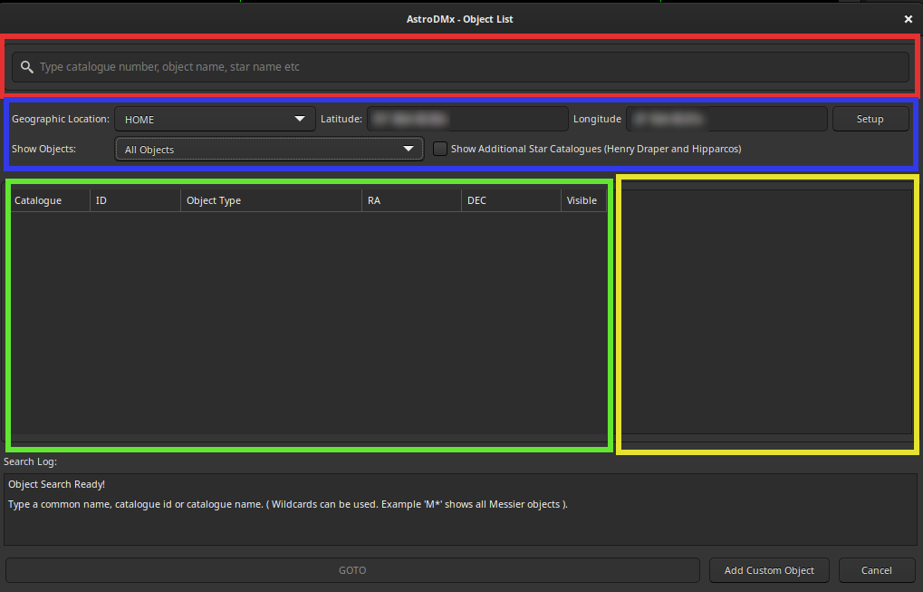
- RED: This is the area where you type an object name. It is possible to type a common name or a catalogue number. Typing in this area will show a list of objects (in the green area) that match the words typed.
- BLUE: This area controls which objects are displayed. If you specify an accurate geographical location and set “Show Objects” to “Geographical Location”, then only objects that are visible from your location will appear in the green area.
- GREEN: This area shows a list of objects that match the word typed. To use a specific object, you left-click the mouse to select the object of interest.
- YELLOW: This area shows details about the object selected from the green area.
It is possible to use wildcards in the search area. For example, if you wanted to see all Messier objects, then you would type M*. Note that searching a large catalogue, such as NGC, then this search could take some time to complete. In the case of a huge catalogue such as NGC it is probably not a good idea to use wildcards.
The following screenshot shows the star, Mizar, being selected. As you can see, only the first two letters of Mizar have been entered but the object list functionality shows all objects that match the letters, ‘mi’.
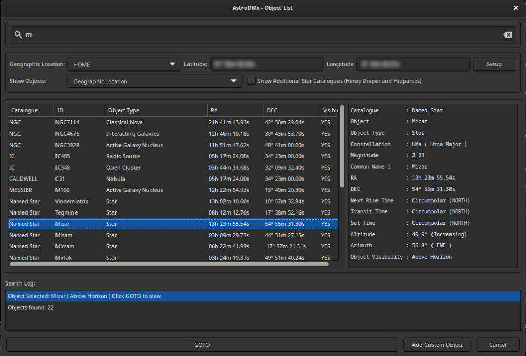
Once an object has been selected, click the “GOTO” button. Once clicked, AstroDMx will complete a few checks to make sure that it is possible to go to the object and then will slew the mount. You will be informed if the GOTO has not been possible.
If slewing during daylight hours, you will see a message warning you that the sun is above the horizon. For the purpose of this simulated walk-through, just click “YES”.
Sun
The GOTO functionality of AstroDMx Capture has solar protection built in. If the sun is above the horizon, then every slew will warn the user before moving the scope. If a slew will take the scope to within two degrees of the sun, then another warning message will be shown.
Despite this protection, it is still the user’s responsibility to make sure that the scope never points at the Sun unless the Sun is the intended target. Of course the correct filters or caps should be placed on the scopes or finder that are on the mount.
This concludes the section on the object database.
10: Slewing, Nudging and Parking
Let’s now slew the simulated mount to the star, Mizar.
The Procedure
- Under the “Controls: Mount” group, you should see a button labelled “Object List”.
- Click “Object List”. This will bring up a new window which will allow you to search for an astronomical object.
- In the search field (at the top of the window) type Mizar (or part of the name).
- This will populate the box under the geographical location area which should show “Mizar” together with the object type and its celestial coordinates.
- Highlight this entry by clicking on it. This will populate additional information on the right hand side of the window. This information includes the following:
- Catalogue Name
- Object Name
- Object Type
- Constellation
- Magnitude
- Common name
- RA and DEC
- Rise, set and transit times
- Altitude and Azimuth data
- Object Visibility. (above or below the observers local horizon)
- Click GOTO at the bottom of this window to slew the mount to the star, Mizar.
NOTE: If you are too far south then the star Mizar might not be visible from your location. If so, just search for another star and use that for the purpose of this work-through.
After completing the steps above, the object selection window will disappear and you will be returned to the main window of AstroDMx. You should see a rotating icon which indicates that the mount is slewing.
Once the slew is complete, the rotating icon will vanish and after a few seconds you will see a double star somewhere close to the centre of the preview screen. This should be the star, Mizar. You should also see that the “Object Info” information has changed to “Mizar: Circumpolar”. If Mizar is not circumpolar from your latitude, then this will give its transit or set time.
The mount is now tracking Mizar and, if one wished, this star could be imaged. However, if you were to switch a reticle on, (with a real star you may notice that the star is not centred, in fact, it may be outside the field of view; but with the simulator it should be centred). We can correct any mis-centring shortly by using the astrometric functionality of AstroDMx Capture.

Before we move onto astrometry (plate solving) we will take a short detour and look at the mount nudge functions. As discussed above, the nudge functions can be found in the “Controls: Mount” group and consist of five buttons.

If you click one of the arrows you should see the preview screen stars move. The nudge functions need to be used in conjunction with the slew rate controls to optimise the speed of movement. If this was a real mount instead of a simulated mount, then this functionality would move the actual mount motors in the same way as the arrows do on a hand controller.
The Procedure
- The “Slew Rate” control should currently be set at “Find”. The exact values in this drop-down menu will be different for different types of mounts.
- Change this to “Guide”. Guide is the slowest slew rate for the simulated mount.
- Press the “UP” arrow and watch the preview screen for about 20 seconds. You should see Mizar moving away from the centre. Remember, our exposures are 5 seconds so it will take at least this length of time to see any movement.
- Press the “STOP” button to terminate this movement.
- This can be repeated for the other arrow controls.
- Once you have finished experimenting with these controls, you can press the “GOTO” button. This will cause the mount to go back to the original coordinates of Mizar and so centre Mizar on the preview screen.
NOTE: You must always press the “STOP” button otherwise the mount will continue to move.
Parking/Unparking Mounts
At the end of an imaging session, a mount must be parked. AstroDMx provides the same functionality to park mounts as the hand controller offers. There are often various parking modes but the usual one is “Default”. Default will return the mount to its native park position.

The Procedure
- Under “Park Mode” select “Default”
- Click “Park Mount”
The mount will now slew to its native parking position. This may take a few minutes to complete and when complete, all the controls in this group will become disabled and the “Park Mount” button’s label will change to “Unpark Mount”.
In order to use the telescope mount again, it will need to be unparked. To unpark, simply click the “Unpark Mount”. This will unpark the mount and all the controls will become available again.
The Procedure
- Click “Unpark”
This concludes the section on Slewing, Nudging and Parking
11: The Equipment Database
Navigate to the top of the controls window on the left hand side and click on the “Equipment” button located in the “General” control group.

Clicking on the “Equipment” button will show the equipment profile window. This functionality can be used to maintain a database of all your telescopes. In this walk-through, we are using the INDI simulators so will add a simulated telescope. If you were doing this for a real telescope, you would add the parameters specific to your telescope. The Equipment Profile window looks like this:

As mentioned in the “Configure the INDI Simulators” section, we are using a simulated telescope with the following parameters.
- Focal Length: 500mm
- Aperture: 80mm
- No barlow lenses
- No focal reducers
Click the “Add New” button to add a new telescope which will show the following window.

The Procedure
- Under “Profile Name” type: “Simulated Telescope”
- Under “Focal Length” type: 500
- Under “Aperture” enter 80
Once you have completed the steps detailed directly above, the window should look like this.

Once you have entered the details about the simulated telescope, click “Add Equipment”.

You can enter as many telescopes, barlows and focal reducer combinations as you need. If entered, the information here will be used to calculate telescope field of view for the plate solver and will also be added to the capture log file.
Finally we need to activate this telescope, so click “Set” to do this. Finally, click “OK” to close this window.
Keep AstroDMx Capture running as this will be needed after setting up the plate solver.
This concludes the section on the Equipment Database.
12: Astrometry (Plate Solving) Setup
AstroDMx Capture now has the ability to perform precise GOTOs via an astrometric plate solver.
The Concept
The GOTO functions of many mounts are not particularly accurate. This is especially true if a mount has not been polar aligned accurately or the star alignment was not accurate. While most mount GOTO systems are accurate enough to position an object somewhere in the field of view of an eyepiece, they are not so good at placing an object onto the relatively small sensor of many astronomical cameras. If so, the object is considered to have been missed.
Astrometry (plate solving) is a way to eliminate this problem. This is how it works:
- The mount is sent to a specific right ascension and declination.
- Due to alignment issues, the telescope will point to where it “thinks” this position is. However, this is often incorrect.
- An image is captured of the starfield
- This starfield is analysed to discover the actual right ascension and declination of the centre of the field of view.
- A difference factor is calculated from astrometry and the coordinates of the object of interest.
- The corrected right ascension and declination are sent to the mount. The mount then slews to the corrected position and, as a result, the object should be dead centre on the camera’s sensor.
AstroDMx Capture version 2 now has this functionality but it must be set up correctly before it can be used. The set up is not complex but does require a few steps. We will now continue with the walk-through and detail the set up steps.
We will break the steps up into logical groups.
Stage 1: Downloading ASTAP
AstroDMx Capture currently uses the ASTAP astrometic plate solver. Other plate solvers are in development and will be released in due course. ASTAP is available for Windows, Linux (x86-64), Linux (arm) and macOS. There are various downloads but the one that must be downloaded for AstroDMx Capture to work is called “astap_cli”.
To download ASTAP, follow this procedure.
The Procedure
- Click on the following link: https://www.hnsky.org/astap.htm (Opens a new tab)
- Navigate down to the section “Alternative Links & development Version”
- Download “astap_cli” for your operating system and place it into a directory (folder) called “ASTAP”.
- Download “H18” zipped star database and place this into the same directory as you placed “astap_cli”.
- Unzip the star database whilst keeping the extracted files in the same directory as you placed “astap_cli”.
Completing the steps above should give you a fully operational ASTAP solver. Once you have done this, we will need to tell AstroDMx where ASTAP is located.
Stage 2: Configuring Plate Solving
Under the “Controls: Mount group”, click on the button labelled, “Precise GOTO (Astrometry). This will open the plate solver control window.
The plate solver UI consists of two tabs.
Tab 1: Plate Solver Setup

The first tab, labelled “Plate Solver Setup”, is used to configure the solver and set various parameters. Generally speaking, you will only need to change the focal length value here as all other values are automatically populated from the hardware currently in use. It is not a requirement to use INDI cameras for astrometry as this functionality will work for natively connected cameras as well.
When this window is started for the first time, it will show that ASTAP is not functioning. This is because we have not completed the setup.
Select the “Plate Solver Setup” tab. The various controls on this tab are grouped into three logical sections. The first is the ASTAP setup functionality, the second is the telescope, camera, pixel size and resolution group and the final is a timeout value for plate solving.
The Procedure (ASTAP Setup)
- Under the top group, click on the “Change Path” button. This will open a file selector. Use this selector to find the “astap_cli” executable file that you downloaded in the previous section.
- Select astap_cli and open it.
- The file selector window will close and you will be returned to the previous window. If this has been successful, you should see a green light to the right of “ASTAP State” as well as seeing some version information which has been returned from ASTAP.
- Set a search radius for ASTAP. This is how much sky ASTAP will search during plate solves. The default value is 20 degrees.
- The “Temporary Save Path” value can be changed but it’s usual to leave this at the default value.
The Procedure (Equipment Setup)
Most of the controls in this group are populated automatically from your connected camera. However, we will need to specify the telescope’s focal length. This is required so that AstroDMx Capture is able to correctly calculate the field of view. The telescope’s focal length can either be entered manually or selected from the equipment database detailed in the equipment database section.
- Under “Telescope/Equipment” use the drop-down list to select “Telescope Simulator”. This value was added in the previous section entitled, “Equipment Database”.
- Once you have selected “Telescope Simulator” you will see its focal length displayed and that various other parameters have been calculated.
Tab 1 will look something like the following screenshot when completed. The most important thing to do now is to check the log at the bottom of the window and look for “[SOLVER] Astrometry is Ready”. If you see this notice, then AstroDMx is ready to solve starfields based on the simulated telescope’s field of view.

You should notice the resolution, focal length, pixel sizes and field of view values are now populated. In addition to this the ASTAP State light should be green.
We are now ready to actually solve starfields.
Stage 3: Plate Solving
Click on the tab labelled, “Solve Field and Correct Mount”.

Let’s have a closer look at each section of this window.
Yellow Group
This group holds the target coordinates. The target coordinates, in J2000, are the exact coordinates of the celestial object that you wish to observe. In the example above, the target coordinates are RA 13h 24m 2s, DEC 54d, 55m, 31 seconds and are for the star, Mizar.
The target coordinates can be obtained from AstroDMx Capture’s internal object database, entered manually or obtained from solving a previously saved image.
To clarify, the target coordinates are the coordinates where you wish the telescope to point at and will actually point at once the solving has successfully completed. If you were to use Stellarium along with AstroDMx Capture, you would notice that, once plate solving had completed, the reticle in Stellarium would no longer be pointing at the exact object. That is to say, it would be offset. The amount of the offset would be consistent with the error of your telescope alignment.
Blue Group
The button controls in this group of controls can be used to populate the target coordinates.
- Get Database Coordinates: This opens the object database.
- Get Mount Coordinates: Pulls the current coordinates from the telescope mount.
- Get Image Coordinates: Obtains coordinates from a previously saved image.
Red Group
This button starts the astrometric routines.
Once this button is pressed, AstroDMx will capture one image and then start the astrometric calculations. Once calculated, the astrometric coordinates will be compared with the coordinates that the mount “thinks” its pointing at and then AstroDMx will calculate the offset and send the mount to the new, corrected coordinates.
For now, simply click “CLOSE” at the bottom of the window. The next section will detail how to solve starfields and automatically correct the mount’s pointing position.
This concludes the section on setting up Astrometry.
13. Astronomy Plate Solving Introduction
Now that we have a functional plate solver in AstroDMx Capture, we are ready to perform plate solves to correct our mount. As we have done in previous sections, we will use the simulators to help demonstrate how this is done.
The Procedure 1
We are going to perform another Mizar GOTO just to make sure that the celestial coordinates haven’t been changed during your experimentation.
- Under the “Controls: Mount” group, select “Object List”.
- Type Mizar into the search area of this window.
- Highlight Mizar.
- Click GOTO.
- Once the GOTO completes, you should see a double star in the centre of the preview screen.
Now we are going to deliberately offset our mount to simulate a GOTO miss. Let’s turn on a reticle to better visualise the centre point of the preview screen.
The Procedure 2
- Go to the main drop down menus (at the top of AstroDMx Capture).
- Click on “Markers and Guides”.
- Navigate down to “Reticle Type”
- Select “Concentric Custom”
- Select “Show Reticle”
This should show a reticle with various circles on the preview screen. In the centre of these circles you should see the double star, Mizar.
The Procedure 3
We will now nudge the mount to simulate a GOTO miss.
- Under the “Controls: Mount” group, you should see a “Slew Rate” control.
- Change the slew rate to “Find”.
- Under the same group, you should see four arrows and a “STOP” button.
- Click one of these arrows and watch the star field change.
- Leave this for about 10 seconds and then press the “STOP” button.
- You should see that the star, Mizar, has vanished from the preview screen.
Let’s imagine that this was a real telescope and that you actually wanted Mizar to be in the centre of the screen. You could, of course, use the arrows to hunt around the area to find the star but this would be difficult and time consuming. The simplest way to do this is via Astrometry.
We will now find Mizar again and re-centre automatically.
The Procedure 4
- Under the “Controls Mount” group, click the “Precise GOTO Astrometry” button.
- Click the “Solve Field and Correct Mount” button.
AstroDMx will now capture an image of the current starfield and perform various astrometric calculations. These calculations will show AstroDMx exactly where the mount is actually pointing and using that information together with the user’s target coordinates, a correction value will be calculated and then sent to the mount. (In a real rather than simulated situation, an exposure/gain combination must be selected to give enough stars for plate solving to work).
Once Procedure 4 is complete, you will see a message that looks like this.

This message is informing you that the starfield successfully solved and it is giving details of the pointing error. In my case, the pointing error was RA 1h 22m 58s, DEC -0d 0m 48s. Remember, this is a simulated pointing error so yours will be different depending upon which nudge button you pressed and the duration of the nudge.
Clicking “YES” will slew the mount to the new, corrected coordinates. Click “CLOSE” on the Astrometry window and watch the preview screen. You should see Mizar reappear in the centre of the screen.
Had this been a real object, such as a nebula or galaxy, the field of view would now be centred on the target coordinates of the object. If there has been a large pointing error then it might be necessary to run the solver again to get it as close to the centre as possible.
This concludes the plate solver introduction
14: Conclusion
This walk-through should give you a grounding on how to use the new functionality of AstroDMx Capture. The walk-through has specifically used INDI simulators but is just as relevant for any INDI driver. It should therefore be possible to use this walk-through on real equipment but instead of adding the INDI simulators in section 4, entitled, “Configuring an INDI server”, you add the actual device drivers for your equipment. The rest remains the same.
AstroDMx Capture can be downloaded from the main downloads section of this website.